Learning how to read structural steel drawings becomes easier when you focus on the purpose of each sheet. These drawings guide fabrication and installation, so clear reading supports safer work and fewer mistakes.
At Henry H Construction Inc, we help project teams turn complex steel information into clear field decisions. Knowing drawing types, symbols, views, and review steps helps general contractors coordinate work with confidence.
Shop Drawings and Design Drawings Serve Different Purposes
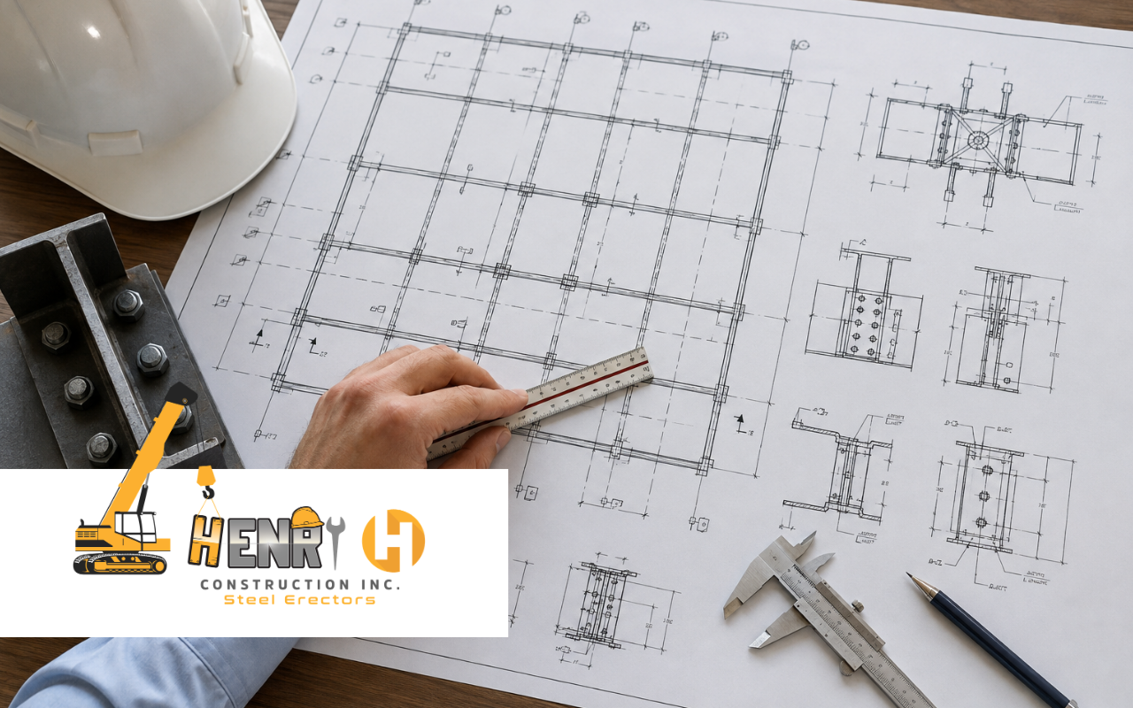
The shop drawing vs design drawing difference starts with intent. Design drawings show the engineer’s overall plan, member sizes, dimensions, and performance needs. Shop drawings explain how each piece will be made, connected, and installed.
When learning how to read structural steel drawings, treat design sheets as the big picture and shop sheets as the working instructions. Reviewing both helps confirm that fabrication follows the engineer’s intent.
- Design drawings show structure, loads, and main dimensions.
- Shop drawings show cuts, holes, bolts, welds, and assembly details.
- Approved shop drawings guide fabrication and field installation.
Steel Symbols and Abbreviations Keep Drawings Clear Daily
Structural steel drawing symbols and abbreviations explained in the legend can save time during every review. Common notes identify plates, welds, bolts, elevations, and repeated conditions.
Always check the legend because abbreviations can vary between projects. Our structural steel detailing guide also shows how clear details support fabrication and field coordination.
- TYP usually means a condition is typical or repeated.
- AFF means above finished floor.
- PL commonly identifies a steel plate.
- Weld symbols show type, size, and location.
Plan Views Show Steel Locations Across Each Level
A plan view looks down on the building and shows where beams, columns, braces, openings, and grid lines sit. It is a useful starting point when learning how to read structural steel drawings because it shows horizontal locations.
Follow grid lines first, then compare member tags, dimensions, and notes. Openings for stairs, ducts, and other systems may appear here. These references help general contractors check steel locations against architectural and mechanical work before installation begins.
Elevation Views Explain Heights Bracing and Vertical Relationships
Elevation views show the structure from the side. They explain floor heights, beam levels, column lengths, roof slopes, braces, and support points. This makes what GCs need to understand in steel drawings easier to see.
Compare elevations with plan views to confirm that horizontal and vertical information matches. This can reveal clearance problems or support conflicts early. At Henry H Construction Inc, we use this cross-checking approach to support smoother coordination before field work starts.
Sections and Details Clarify Connections Hidden From View
Sections show relationships that plans or elevations cannot display clearly. Details then zoom in on connections, plates, bolt spacing, weld locations, stiffeners, and other important parts that affect how steel members fit together.
Use reference bubbles and sheet numbers to move between the main drawing and related details. When you know how to read structural steel drawings, these views help check connections and avoid fabrication mistakes.
- Match section marks with the correct sheet.
- Check plate sizes and connection notes.
- Confirm bolt spacing and weld information.
- Compare details with member tags on plans.
Material Schedules Help Teams Track Every Steel Piece
Material schedules organize members, plates, sizes, grades, lengths, and finish notes in one place. Matching each drawing tag to the schedule helps teams confirm what must be ordered, fabricated, and installed.
Schedules also support shop drawing review because they make missing or changed items easier to catch. Our steel shop drawing support is useful when detailed coordination is needed before fabrication.
Frequently Asked Questions
Why are structural steel drawings important during construction?
They show where steel members go and how they connect. Clear drawings support fabrication, installation, inspections, and coordination while reducing field mistakes.
What is the main shop drawing difference?
Design drawings show the engineer’s intent, while shop drawings show how individual steel pieces will be fabricated and assembled. Both must work together before fabrication can move forward.
Which drawing should a general contractor review first?
Start with the design plans to understand the overall structure. Then review shop drawings, elevations, sections, schedules, and details together to spot conflicts.
How do symbols make steel drawings easier?
Symbols replace long written notes with standard visual instructions. Structural steel drawing symbols and abbreviations explained in the legend help teams read welds, plates, bolts, levels, and repeated conditions more quickly.
Can software make drawing review more reliable?
Yes. Digital viewers and 3D models can clarify complex areas. However, teams still need to understand how to read structural steel drawings so they can verify notes, dimensions, connections, and revisions correctly.
Careful Drawing Review Supports Smoother Steel Construction Projects
A strong review process connects design intent with fabrication and field work. Compare member sizes, dimensions, connections, openings, and site conditions before shop drawing approval. This helps teams catch issues before they become costly changes.
With Henry H Construction Inc, our team supports clear coordination from review through steel execution. Review our construction and steel services or get in touch with us to discuss your project.